
5-axis machining
Compound angles · single setup

Milling, drilling and routing PMMA sheet and block on 8× 3-axis and 1× 5-axis centers — annealed, polished-ready, prototype to production.
Reply within 12 hours · free DFM feedback
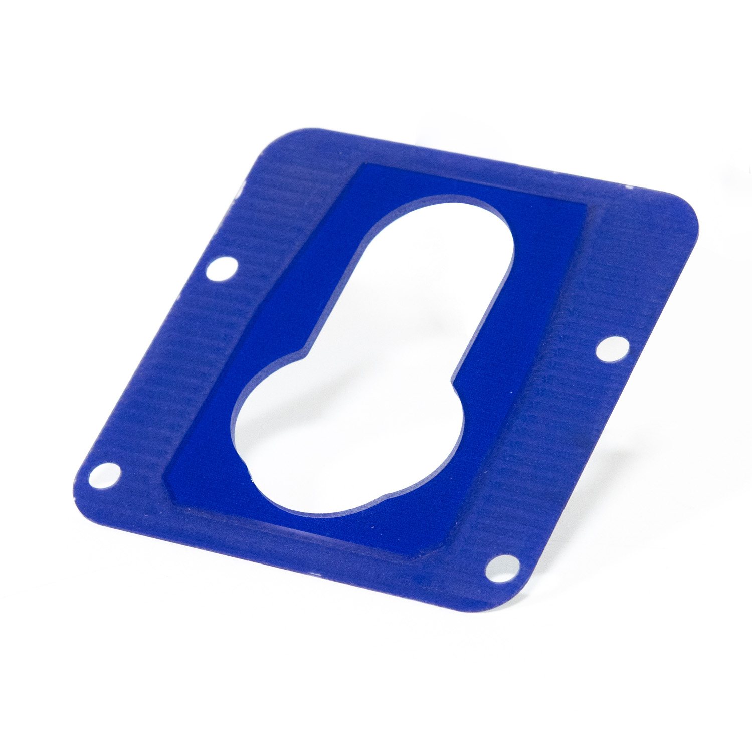
CNC acrylic machining is the milling, drilling and routing of PMMA sheet or block on computer-controlled machining centers. Done correctly — sharp single-flute tooling, high spindle speeds, controlled feeds and post-machining annealing — it holds tolerances of ±0.05 mm and leaves edges clear enough to polish to full transparency.
Equipment & capacity
| 3-axis CNC machining centers | 8 · working envelope up to 3000 × 2000 mm |
| 5-axis CNC machining center | 1 · 1200 × 1000 × 500 mm · angled features & complex geometry in one setup |
Compound angles · single setup

Sharp tooling · polished-ready edge

±0.05 mm · annealed
| Tolerance | ±0.1 mm standard, ±0.05 mm critical |
| Thickness | 3–100 mm |
| Min feature | Ø1 mm holes, 1 mm slots |
| Surface finish | Machined, then flame / diamond polished per drawing |
| Threads | Tapped holes ≥ M3; brass inserts for repeated assembly |
| Files accepted | STEP, IGES, DWG, DXF, PDF |
Why acrylic machining is its own skill
Single-flute polished carbide, swapped on schedule not on failure.
Speeds set per thickness to cut, not melt the edge.
Corner radii ≥ tool radius designed in — sharp internal corners crack.
Eliminates crazing when parts later meet solvents or load.
On every new drawing, before production releases.
±0.1 mm routinely, ±0.05 mm on critical dims. Tighter is possible but usually wasted — acrylic’s thermal expansion (~0.07 mm/m/°C) exceeds micron tolerances across normal temperature swings.
Acrylic (PMMA) is our specialty. We machine Acrylic (PMMA) and polycarbonate (PC) only; we do not fabricate PVC, PETG or HDPE.
48 hours from approved drawing for typical parts, plus shipping.
Residual machining stress plus solvent exposure causes crazing. Annealing prevents it — which is why it’s standard in our process, not an upcharge.
STEP, IGES, DWG, DXF and PDF, or a dimensioned sketch and photos of the part; if there is no CAD file, our engineers draft a manufacturing drawing for your approval.
Each drawing is held under your part number with version control, and a revision change triggers a new first-article inspection so production always matches the approved revision.
Residual machining stress plus solvent, fastener or load exposure causes crazing; annealing with the cast-acrylic industry-standard schedule reduces that risk, which is why it is standard in our process, but it does not guarantee the part against every service condition.
Every new drawing gets a first-article inspection of the critical features, and reorders run on the same CNC programs with the material grade locked to the part number.
Yes, with a review first. STEP, IGES, DWG, DXF and PDF drawings are accepted, or a dimensioned sketch with sample-part photos; engineers can produce a manufacturing drawing from a sketch when no CAD file exists. Every new drawing passes a manufacturability review before quoting: material, datums, hole positions, mating faces, radii and critical dimensions.
Drawing-called critical dimensions are confirmed on the 5-axis center at ±0.05 mm against the drawing plus first-article inspection; general tolerances follow GB/T 1804-2000 / ISO 2768 and vary with size span, and holes and machined features are quoted at ±0.1 mm. Inspection uses calibrated measuring tools, and the method for critical features is confirmed per order.
Machined parts are annealed with the cast-acrylic industry-standard schedule to reduce residual stress; specific temperature and soak values are confirmed per grade, not published. Annealing reduces but does not eliminate cracking risk, so aggressive solvents, sustained load, fasteners or thermal cycling need a design and process review before quoting.
Send your CAD file for free DFM feedback within 12 hours.
Technical details
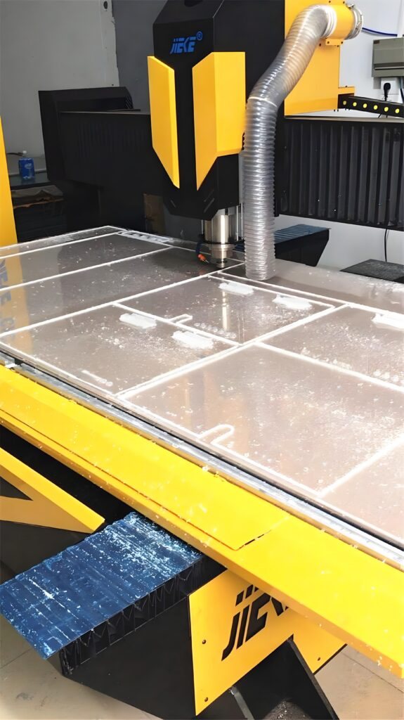
CNC router cutting a large clear acrylic sheet on a flatbed
Close-up of a precision machined clear acrylic component
Technical details
Company-declared
Every new drawing passes a drawing review for manufacturability before quoting: material and thickness, datum features, hole positions, mating faces, corner radii, wall sections and which dimensions are critical are confirmed and listed on the quote.
Technical details
Sharp single-flute tooling replaced on schedule, feeds tuned per thickness, DFM corner radii and first-article inspection on every new drawing are the process rules that keep machined features clean and repeatable.
Drawings are held under your part number with version control; a revision change triggers a new first-article inspection so production always matches the approved revision.
General tolerances follow GB/T 1804-2000 / ISO 2768 and vary with the size span; holes and machined features are quoted at +/-0.1 mm, and drawing-called critical dimensions on the 5-axis center are confirmed at +/-0.05 mm against the drawing plus first-article inspection.
Machined parts are annealed as standard with the cast-acrylic industry-standard schedule to reduce residual stress before bonding or final finishing; annealing reduces but does not eliminate the risk of crazing or cracking.
| Choose this when | Do not choose this when | Tolerance | Claim IDs |
|---|---|---|---|
| The feature is a hole, slot or machined feature with no tighter call-out | The feature is a mating face or critical dimension with a drawing call-out | General tolerance per GB/T 1804-2000 / ISO 2768 by size span; +/-0.1 mm typical on holes and machined features | AF-C03, AF-C01 |
| Your drawing calls out a critical dimension that controls assembly fit | The dimension is a standard feature already covered by general tolerance | Critical dimension at +/-0.05 mm on the 5-axis center, confirmed per drawing plus first-article | AF-C02 |
| The part exceeds the confirmed scope for a tolerance class | The part fits within confirmed size and thickness ranges | Tolerance agreed per drawing and first-article; no blanket full-part band |
| Choose this when | Do not choose this when | Readiness | Claim IDs |
|---|---|---|---|
| You have a CAD model or dimensioned drawing | You only have a vague concept without dimensions | Send STEP, IGES, DWG, DXF or PDF for review | AF-C14 |
| You have a sketch or sample part only | The geometry must be exact and no sketch is possible | We draft a manufacturing drawing for your approval | |
| The part will be bonded, threaded or fitted to other components | The part is standalone with no assembly interfaces | Confirm mating faces and datums in the drawing |
| Property | Value | Unit | Product grade | Thickness specimen | Test method / standard | Evidence status | Qualification | Claim IDs |
|---|---|---|---|---|---|---|---|---|
| General tolerances | GB/T 1804-2000 / ISO 2768, class varies with size span | n/a | Cast and extruded acrylic | 3-100 mm | GB/T 1804-2000; ISO 2768 | company-declared | Grade and size-span mapping pending | AF-C03 |
| Machined feature tolerance | +/-0.1 mm on holes and machined features | mm | Machined acrylic | 3-100 mm | Dimensional inspection per drawing | company-declared | Applicable hole diameter and thickness range pending | AF-C01 |
| Critical dimension tolerance | +/-0.05 mm on drawing-called critical dimensions via the 5-axis center | mm | Machined acrylic | Order-specified | Drawing call-out plus first-article inspection | company-declared | Critical-feature definition and size cap pending; never a full-part band | AF-C02 |
| Fabrication thickness range | 3-100 mm | mm | Cast and extruded acrylic | Sheet and block | Company statement | company-declared | Cast versus extruded ranges pending | AF-C05 |
| Minimum machined feature | 1 mm holes and slots | mm | Machined acrylic | Order-specified | Per drawing and tooling | selection guidance | Confirmed per geometry and thickness | |
| Threads | Tapped holes from M3; brass inserts for repeated assembly | n/a | Machined acrylic | Order-specified | Per drawing | selection guidance | Thread engagement confirmed per thickness |
| Property | Value | Unit | Product grade | Thickness specimen | Test method / standard | Evidence status | Qualification | Claim IDs |
|---|---|---|---|---|---|---|---|---|
| Annealing schedule | Cast-acrylic industry-standard schedule applied to machined parts | n/a | Cast acrylic | Order-specified | Company process statement | company-declared | Specific temperature and soak parameters not published | AF-C10 |
| Annealing outcome | Reduces residual stress and crazing risk | n/a | Machined acrylic | Order-specified | Company process statement | company-declared | Does not eliminate cracking risk; service conditions still matter | AF-C10 |
| Solvent and bonding exposure | Annealed parts are preferred for solvent bonding; flame-polished edges are annealed before bonding | n/a | Machined acrylic | Order-specified | Company process guidance | selection guidance | Confirmed per application | |
| Fastener and load conditions | Residual stress plus sustained load or aggressive solvents can still cause crazing | n/a | Machined acrylic | Order-specified | Company process guidance | selection guidance | Design review per application |
Q: What tolerance can you hold on machined acrylic parts? A: Our 3-axis and 5-axis CNC centers machine PMMA to tolerances of ±0.1 mm on typical features, with tighter control on critical dimensions called out on your drawing.
Q: Do you offer 5-axis CNC machining for acrylic? A: Yes. We run a 5-axis CNC machining center alongside eight 3-axis centers, which lets us machine complex contoured and multi-face PMMA parts in a single setup.
Q: Cast or extruded acrylic for CNC machining? A: Cast acrylic machines cleaner with lower internal stress and less chipping, so it is preferred for precision machined parts; extruded acrylic is used where thickness consistency and cost matter more than tight tolerance.