
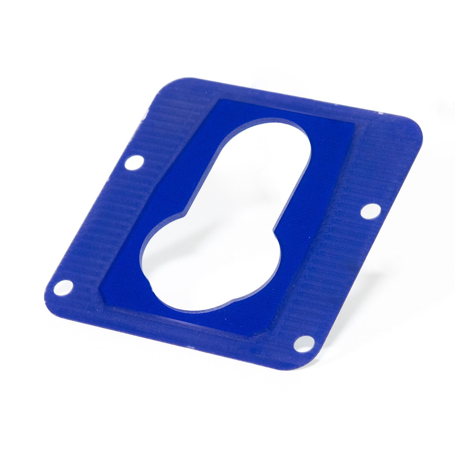
Acrylic CNC Machining Tolerances: General vs Critical Features, Size Dependence and Inspection
This guide separates general tolerances from drawing-called critical tolerances so you can specify acrylic CNC parts without over-tolerancing.
Reply within 12 hours · free DFM feedback

Tolerances depend on part size and are confirmed per drawing plus first-article inspection; no value applies to all sizes.
Company-declared
How general tolerances shift with size
General tolerances per GB/T 1804-2000 / ISO 2768. The tolerance changes with the size span of the dimension, so the mapping is confirmed at drawing review per order: no single value is correct for every size.
Working bands for machined features
Machined features to ±0.1 mm (holes and machined features) is the standard working band we quote, and critical dimensions on the 5-axis CNC to ±0.05 mm are confirmed against the drawing plus first-article inspection; critical means hole position, mating faces or profiles that affect assembly.
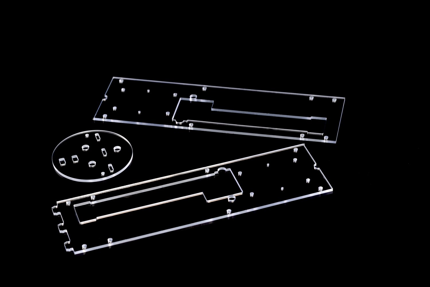
CNC-machined acrylic panel with milled channels and pockets
CNC-machined acrylic panel with milled channels and pockets
When a dimension is critical
A dimension is critical when a deviation stops the part from assembling or meeting its function; general dimensions control basic geometry and carry the standard tolerance, so putting every dimension at a critical band usually raises cost without improving the part.
Inspection and first-article checks
Inspection is performed with calibrated measuring tools and, for critical features, the measurement method and equipment are confirmed per order; first-article inspection documents the measured values before production continues.
What limits achievable tolerance
Part size, thickness and geometry affect what is achievable: deep pockets, thin walls and long spans are reviewed in DFM, and the achievable tolerance for each feature is confirmed on the quote rather than assumed.
General versus critical tolerance: which callout applies
| Choose this when | Do not choose this when | Option | Claim IDs |
|---|---|---|---|
| The dimension controls assembly or function | It is a basic geometry dimension | Call it critical; confirmed per drawing plus first article | AF-C02 |
| Standard hole or machined feature without a tight callout | The drawing calls a tighter critical band | ±0.1 mm working band | AF-C01 |
| You only need basic geometry control | Assembly depends on the dimension | GB/T 1804-2000 / ISO 2768 general tolerance | AF-C03 |
| Long spans, deep pockets or thin walls are involved | Compact features on a stable blank | DFM review; tolerance confirmed per feature | AF-C03 |
Tolerance basis, size dependence and inspection conditions
| Property | Value | Unit | Product grade | Thickness specimen | Test method / standard | Evidence status | Qualification | Claim IDs |
|---|---|---|---|---|---|---|---|---|
| General tolerance basis | GB/T 1804-2000 / ISO 2768; varies with size span | n/a | Order-specific acrylic grade | n/a | GB/T 1804-2000 / ISO 2768 | company-declared | Size-span mapping confirmed at drawing review per order | AF-C03 |
| Standard machined features | ±0.1 mm on holes and machined features | mm | Fabricated acrylic parts | 3–100 mm fabricated range | Calibrated measurement; method per order | company-declared | Scope pending: hole diameter, thickness and material range | AF-C01 |
| Critical dimensions (5-axis) | ±0.05 mm on drawing-called critical dimensions | mm | Fabricated acrylic parts | Per drawing | Drawing plus first-article inspection | company-declared | Not a full-part band; confirmed per drawing and first article | AF-C02 |
| Critical feature definition | Hole position, mating faces, profiles that affect assembly | n/a | Fabricated acrylic parts | n/a | Drawing review | company-declared | Listed on the quote at drawing review | AF-C02 |
| Size dependence | Tolerance changes with the size span of the dimension | n/a | Order-specific acrylic grade | n/a | GB/T 1804-2000 / ISO 2768 | company-declared | No single value applies to all sizes | AF-C03 |
| Inspection equipment | Calibrated measuring tools; method and equipment confirmed per order for critical features | n/a | Fabricated acrylic parts | Order-specified | Agreed measurement method | company-declared process | Equipment models not published | |
| First-article confirmation | Critical features measured on the first part of a new drawing | n/a | Fabricated acrylic parts | Order-specified | First-article inspection report | company-declared process | Report on request; revision triggers a new first article |
Evidence and verification
- Dimensional inspection reports and first-article data are supplied on request per order.
- A certificate of conformity or batch COA can be supplied per order on request.
- Tolerance and process statements on this page are company-declared by AcrylicFabWorks unless stated otherwise.
- Applicable product grade: Fabricated acrylic (PMMA) parts
- Fact owner: Engineering review, AcrylicFabWorks
- Last reviewed: 2026-08-27
FAQ
What tolerance can you hold on CNC-machined acrylic?
Machined features to ±0.1 mm (holes and machined features) is the standard working band; critical dimensions on the 5-axis CNC to ±0.05 mm are confirmed against the drawing plus first-article inspection.
Does ±0.05 mm apply to the whole part?
No: ±0.05 mm applies to drawing-called critical dimensions on the 5-axis CNC and is confirmed per drawing plus first-article inspection; general dimensions follow GB/T 1804-2000 / ISO 2768 and vary with size span.
Do tolerances depend on part size?
Yes: general tolerances per GB/T 1804-2000 / ISO 2768 change with the size span, so the mapping is confirmed at drawing review per order rather than assumed.
How are tolerances verified?
Critical features are measured on the first article with calibrated measuring tools, and the measurement method and equipment are agreed per order; dimensional reports are supplied on request.
What if I only need basic geometry control?
Dimensions that do not affect assembly or function can run under the general tolerance band, which usually lowers cost; the quote lists the tolerance class assumed per feature.
How should I tolerance my acrylic drawing so a machinist can actually hold it?
Call out only the dimensions that affect assembly as critical and leave the rest to general tolerances per GB/T 1804-2000 / ISO 2768, which change with the size span. Putting every dimension at a critical band usually raises cost without improving the part; the quote lists the tolerance class per feature.
Why does tolerance drift on long or thin acrylic parts?
Thin walls, deep pockets and long spans can exceed the working band because material stiffness and machining forces scale with size and thickness. DFM feedback on the quote states what is achievable per feature, and first-article inspection confirms the actual result before production continues.
How is the tolerance on machined acrylic features actually measured?
Inspection is performed with calibrated measuring tools; for critical dimensions the measurement method and equipment are confirmed per order and recorded in the first-article inspection report. General dimensions are verified against the standard’s size-span rules, and the report shows measured values versus the drawing call-outs.
Get a quote
Send your drawing — an engineer replies within 12 hours.
Related
- See the CNC machining capability page for drawing review and process rules
- Read how workholding and fixture design affect machined accuracy
- Check how first-article inspection and dimensional reports are controlled
- Review lead time, warranty and order rules
- Send the drawing with critical dimensions for a tolerance confirmation